
Static resistance tests can miss critical On-Load Tap Changer (OLTC) problems. Learn how Dynamic Resistance Measurement (DRM) reveals issues like contact wear and transition faults before they fail.
For decades, the standard DC winding resistance test has been a staple in assessing the condition of a transformer’s windings. When applied to an On-Load Tap Changer (OLTC), it can verify the integrity of contacts at each tap position. However, this static test has a significant blind spot: it tells you nothing about the health of the tap changer during the transition from one tap to another.
This is where Dynamic Resistance Measurement (DRM), also known as the “make-before-break” test, becomes an indispensable diagnostic tool for the modern technician and maintenance engineer.
What a Static Test Can’t See
A static test applies a DC current and measures the resistance once the OLTC has settled on a selected tap. It can confirm a good connection. What it cannot detect are problems that occur in the milliseconds the diverter or selector switches are moving, such as:
- Contact Arcing: Severe arcing during the transition, indicating worn or misaligned contacts.
- Transition Time Issues: Sluggish or overly fast switching, which points to mechanical problems in the drive mechanism.
- Open Circuits: A momentary break in the circuit during the transition, which can cause catastrophic failure of the transformer.
- High Transition Resistance: Pitting or coking on the contacts that only presents a problem under load and during the switching operation.
Relying solely on static tests is like inspecting a car’s engine while it’s turned off; you miss all the problems that only appear when it’s running.
How Dynamic Resistance Measurement (DRM) Works
DRM transforms the test from a single snapshot into a continuous video of the OLTC’s operation. The process is straightforward:
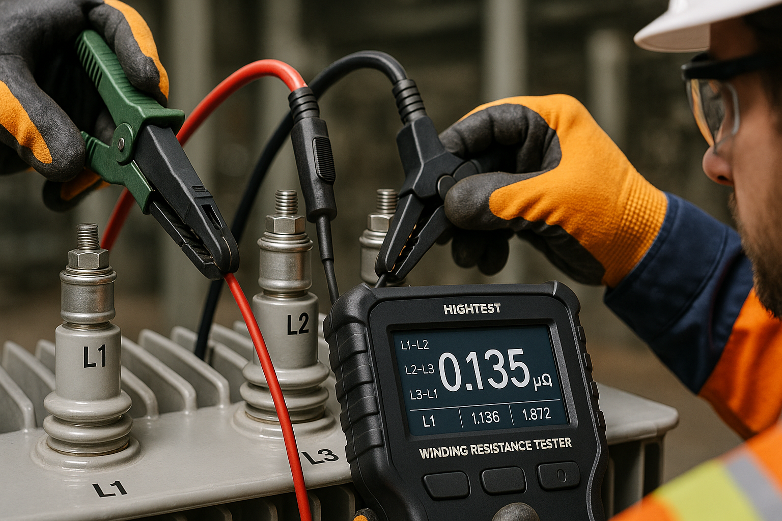
- A DC test current is injected through the winding, just like a standard resistance test.
- The test set is commanded to record while the OLTC is instructed to switch through its taps.
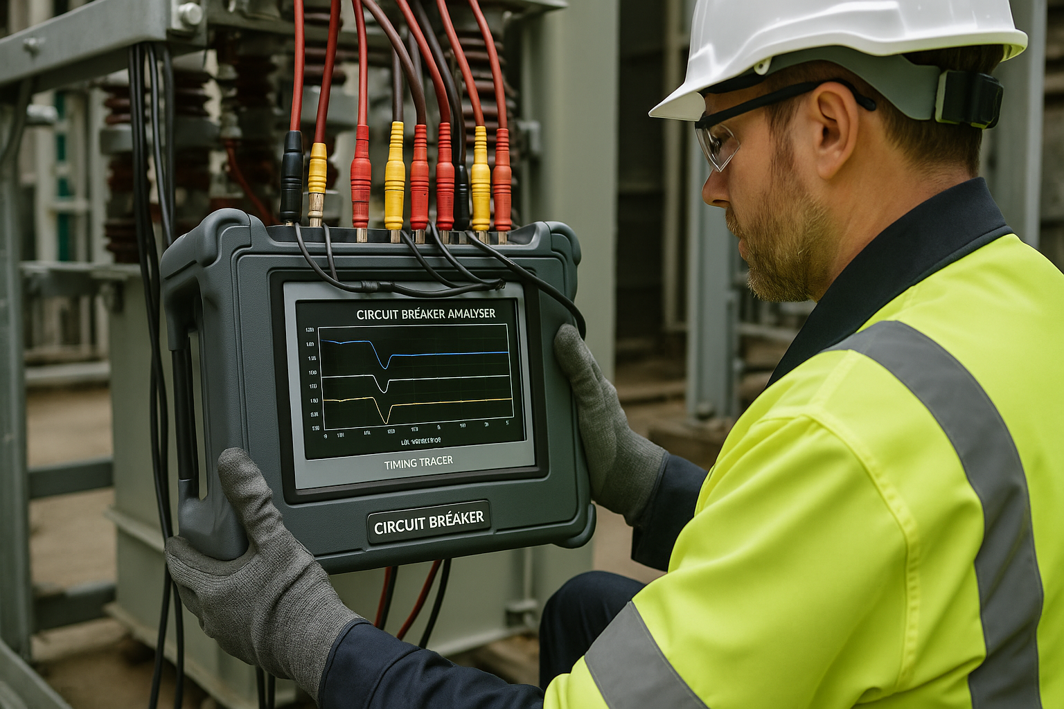
- Instead of a single resistance value, the test set records the current and/or voltage as a function of time, generating a graphical waveform.
This graph provides a wealth of information. A healthy OLTC will show a relatively straight line, with a small, sharp “dip” or “ripple” during each tap change as the diverter resistors are briefly inserted into the circuit.
Interpreting the DRM Waveform
The power of DRM lies in graphical analysis. Deviations from a clean waveform are clear indicators of specific problems:
- An Abnormally Long or Deep Dip: This can indicate a slow-moving contact or high resistance in the transition resistors.
- A Sharp Drop to Zero (Open Circuit): This is the most critical finding. It indicates the “make-before-break” sequence has failed, and the circuit is being interrupted. This OLTC should be taken out of service immediately.
- Excessive Ripple or “Noise”: A noisy or jagged waveform during the steady-state portion points to issues with the OLTC motor current, indicating potential drive mechanism problems.
- Inconsistent Signatures: If the waveform for one tap change looks significantly different from the others, it points to a problem specific to that tap’s contacts.
Conclusion
While static winding resistance remains a valuable test, it is no longer sufficient for a complete assessment of an OLTC’s health. Dynamic Resistance Measurement provides a deeper, more comprehensive diagnostic view, allowing engineers to see inside the tap changer as it operates. By integrating DRM into your routine maintenance testing, you can identify mechanical and electrical degradation before it leads to a costly, unplanned outage, moving from a reactive to a proactive maintenance strategy.