
A transformer’s short-circuit impedance can change due to faults or transport damage. Learn why field verification is key to detecting mechanical deformation before a catastrophic failure occurs.
Every transformer has its short-circuit impedance percentage (%Z) stamped on its nameplate. This value is a critical design parameter, representing the opposition to current flow when one winding is short-circuited. For many, it’s seen as a fixed, unchanging value. However, this assumption can be dangerous.
Significant changes in a transformer’s physical structure, caused by electrical faults or mechanical stress, will directly alter its leakage reactance, and therefore, its short-circuit impedance. This makes the field measurement of short-circuit impedance a powerful diagnostic tool for detecting potentially catastrophic mechanical damage.
What Does Short-Circuit Impedance Really Tell Us?
The nameplate value is determined under controlled conditions at the factory. In essence, it’s a measure of the transformer’s leakage flux—the magnetic flux that does not link both the primary and secondary windings. This leakage flux path is directly dependent on the precise geometry and spacing of the windings and the core.
Any event that alters this geometry will change the leakage reactance and, consequently, the impedance. Such events include:
- External Short-Circuits: The immense electromagnetic forces generated during a close-in fault can physically bend, shift, or compress the windings.
- Shipping Damage: Severe impacts or vibrations during transportation can cause internal structures to move.
- Internal Faults: Turn-to-turn shorts or other internal failures can deform the winding structure.
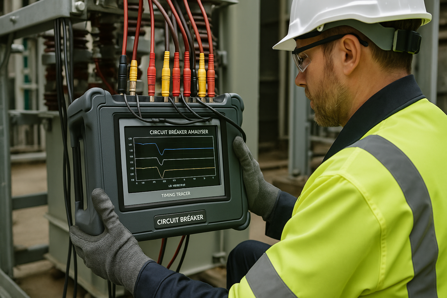
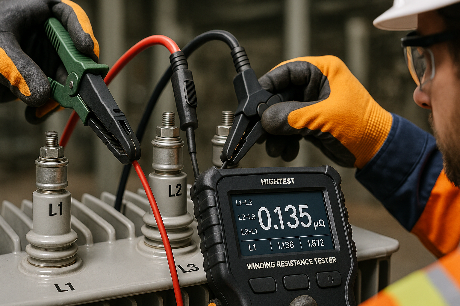
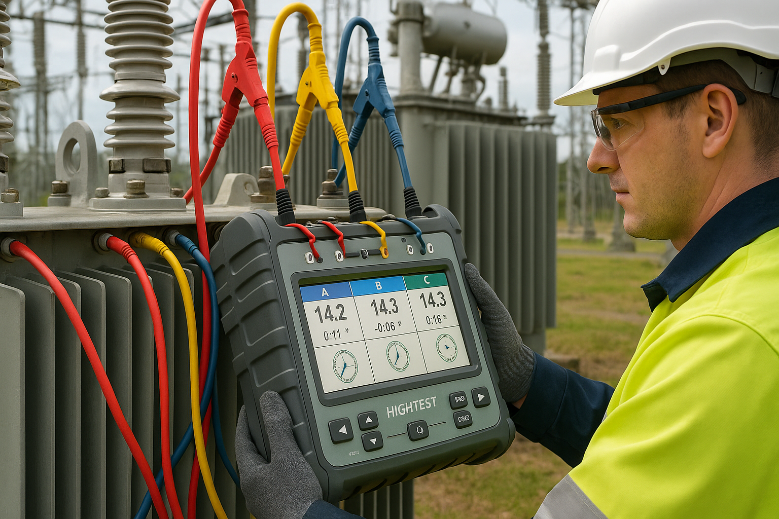
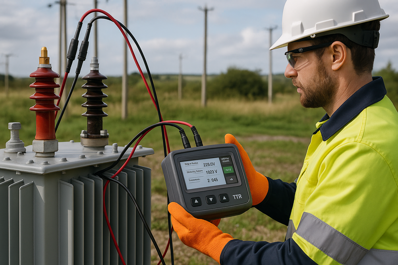
The Field Test: A Simple but Powerful Health Check
Measuring short-circuit impedance in the field is a relatively straightforward electrical test. It involves short-circuiting one set of windings (typically the LV side) and applying a reduced voltage to the other winding until the rated current flows in the shorted winding. The impedance is then calculated from the measured voltage and current.
Modern, multi-function test sets like the HighTest TURA-01 or TURA-03 automate this process, making it fast and safe to perform. They can inject the required voltage and precisely measure the resulting values, providing a direct comparison to the nameplate data.
Interpreting the Results: The ANSI/IEEE Guideline
How much deviation from the nameplate value is acceptable? According to ANSI/IEEE C57.12.90 standards, the measured impedance should not vary from the nameplate value by more than ±3%.
- Deviation within ±3%: Generally indicates no significant mechanical deformation has occurred. The transformer’s internal geometry is likely intact.
- Deviation Greater than ±3%: This is a major red flag. It strongly suggests that the windings or core have shifted or been deformed. A transformer with such a deviation requires further investigation, such as a Sweep Frequency Response Analysis (SFRA), to confirm the extent of the mechanical damage.
Conclusion
Treating the short-circuit impedance as just a static nameplate value is a missed opportunity for critical diagnostics. By incorporating this test into routine maintenance, especially after a suspected fault or relocation, engineers and technicians can gain a vital insight into the mechanical integrity of a transformer. It is a simple, non-invasive test that can be the difference between identifying a problem early and experiencing a major, unplanned failure.