TURA-X

Phase-Shifting Transformer tests

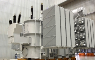
A phase-shifting transformer is a specific form of electrical transformer used to manage the flow of active power on 3Ø electric transmission lines. It is often called a phase angle regulating (PAR) in the US and a quadrature booster in the UK. In this application note, we will use the phase-shifting (PST) term. Physically, phase-shifting transformers are static machines whose general construction characteristics are in some respects similar to conventional transformers with two separate transformers: A Shunt unit or Exciting unit (EU) and a series unit (SU). Due to their internal connections, they make it possible to obtain a phase shift between the input and output voltages. The phase shift between the input and output [...]

Transformer Vector Group Detection

The three-phase transformer comprises three separate single-phase transformers with shared limbs, each representing a phase consists of primary and secondary windings. The primary or secondary windings are connected in one of several ways. The most common configurations are the star, delta, and Zigzag. The phase angle between the high voltage and the low voltage windings varies between 0o and 360 o. The vector group is the method of categorizing the high voltage HV windings and low voltage LV windings configurations of three phase transformers [1]. The vector group of a transformer is presented as follow: Fig.1. Vector Group Representation THE IMPORTANCE OF THE TRANSFORMERS VECTOR GROUP DETECTION. The transformers vector group identification (Y-Y, Delta-Y, Delta-Delta… etc.) is an essential [...]

Transformer Magnetic Balance Test

The magnetic balance test is a most commonly used proactive test is performed only on three-phase transformers to detect the faults in the core and to verify the imbalance in the magnetic circuit also to identify inter-turn faults in the transformer at the early stage of manufacturing work. HOW DO WE TEST TRANSFORMER MAGNETIC BALANCE? Transformer Magnetic Balance Test Procedures: 1. Keep the transformer Tap Changer in an ordinary position. 2. Apply a single-phase AC voltage on one of the terminals of the HV winding. 3. Measure the voltage between the two other HV terminals. 4. Repeat the test for each of the three phases. Left side phase Central phase  Right side phase AN BN CN Voltage applied at [...]

Go to Top