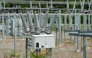
WHAT IS CIRCUIT BREAKER & WHY SHOULD WE TEST IT?

Circuit breakers allow the flow of energy to be controlled by safely switching current on and off at all voltage levels of the energy grid. In the opened position, they have to ensure isolation across the switching distance between phases and to ground, in the closed position, they have to allows the energy to flow with minimum losses. They need to be able to reliably interrupt short circuit currents without damaging themselves or adjacent equipment even after long idling times. Different circuit breaker technologies are in use depending on voltage level, application and the age of their design.

Current interruption takes place in interrupter chamber containing; Air, Oil, Sf6 and Vacuum. Circuit breakers may use multiple contact systems consisting of main contacts and arcing contacts, the main contacts allow operating current to flow with minimum losses while arcing contacts can break short circuit currents with minimum arcing.

The breaking element is usually operated mechanically by a stored energy system. The energy that opens and closes the contacts is typically stored in a spring hydraulic or pneumatic devices or system. the stored energy is released by the trip or the close command signal. The command signal activates the trip enclosed coils, releasing the drive mechanism to perform the opening and closing operation.

The interrupter and the mechanical drive are the main components that are subject to wear and ageing. The thermal stress of load currents may cause corrosion and oxidation, as interruption of short circuit currents erodes the contact system. Environmental stress such as temperature, humidity or contamination affect the bearing and linkage surfaces of the drive. Ancillary components such as bushings are also subject to electrical stress ageing.

In order to ensure the proper operation of circuit breaker throughout its life diagnostic tests are performed such as Static Contact Resistance & Dynamic Resistance and Timing & Travel and Coil Current, … etc, and Vacuum Bottle integrity (see Vacuum Bottle Insulation Integrity Test).

  • Static Contact Resistance & Dynamic Resistance Test (ARES-200)

The static contact resistance in the close position usually is the first test performed on a circuit breaker. It determined by injecting a high DC current while the voltage is measured via a separate set of cables.  If the circuit breaker has multiple contacts, then the measurement of dynamic resistance during the opening and closing will help to detect losses and damage of the arcing contact.

The circuit breaker’s mechanical performance can be verified by analysing the time of opening and closing contacts.

Comparing the obtained results with the factory data or previous measurements which must fall within defined limits, can reveal the faults in the circuit breaker and help us to avoid potentially catastrophic problems in the power lines and substations.

The trip/close coil current gives an indication to understand and monitor the condition of the latch.

Additionally, if the circuit breaker travel curve is recorded it allows mechanical paraments to be assessed such as velocity total, travel, acceleration, over travel and rebound.

By performing these measurements, the station operation can verify that the equipment is in good working condition or can initiate maintenance activities.